


~
2,450
tonnes
Annual CO₂e reduction
~
16
%
Annual natural gas reduction
<
3
years
Payback period
Integrated Heat Recovery from Thermal Oil Heater Flue Gases
The site has no conventional boiler plant, relying instead on thermal oil heaters to heat frying oil and generate steam through separate heat exchangers. Flue gases leave the heaters at approximately 121°C, representing a major opportunity to recover thermal energy otherwise lost to the atmosphere.
Thermal Energy International delivered an integrated system to capture this heat and transfer it into the site’s hot-water circuits. By preheating water for process and utility use, the system reduces the load on the thermal oil heaters, cutting natural gas consumption and associated carbon emissions without disrupting continuous production.
A Two-Stage Heat Recovery System
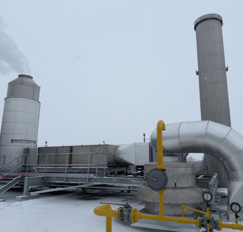
The system combines two recovery stages in series. The HeatSponge™ indirect economiser recovers higher-temperature sensible heat first, before the flue gas enters the FLU-ACE™ condensing stage for the recovery of lower-temperature sensible and latent heat.
First-Stage Heat Recovery from Thermal Oil Heater Exhaust
The HeatSponge™ sits first in the flue-gas path, recovering sensible heat from the thermal oil heater exhaust. On the water side, it raises the temperature of the hot water leaving the downstream FLU-ACE™ condensing stage before the circuit preheats cold reverse-osmosis water entering the deaerator. This arrangement extends heat recovery across the available temperature range while delivering the recovered energy at a temperature suitable for the site’s deaerator makeup demand.
Built as a single, fully insulated unit with integral gas transitions, the economiser incorporates internal baffles and drainage to manage condensate and wash water. Compression-fitted tubes allow individual tubes to be replaced, while two access doors provide direct access for inspection and maintenance.
The flue-gas arrangement was configured to draw exclusively from the thermal oil heater exhaust, maintaining reliable heat-transfer performance. The economiser’s 316 stainless steel construction provides corrosion resistance, while integral drainage limits accumulation within the lower section. A powered rotary soot blower automatically cleans the heat-transfer surfaces on a programmed cycle, reducing fouling and the need for manual cleaning at roof level.
The exposed system was also designed for year-round operation in Canadian winter conditions. Freeze-protection measures and materials validated through stress testing at temperatures down to −20°C support reliable cold starts and reduce freeze risk in exposed piping and drainage components.
Second-Stage Condensing Heat Recovery from the Remaining Flue Gas
Downstream, the FLU-ACE™ direct-contact condensing system cools the remaining flue gas and condenses its water vapour, recovering residual sensible heat and the latent heat released during condensation. The recovered energy is transferred through a dedicated hot-water loop and plate heat exchangers to preheat deaerator makeup and high-pressure hot water.
Coordinated Operation and Production Continuity
An automated heat-recovery management system integrated with the plant’s distributed c coordinates the two recovery stages, manages heat distribution and provides continuous performance monitoring.
The recovery equipment is installed in a parallel flue-gas path, allowing the exhaust to vent normally when the recovery system is unavailable. This preserves thermal oil heater operation and avoids making production dependent on the heat-recovery equipment.
Designed for Future Heat Integration
The system has been designed with capacity to recover additional heat as the site develops further uses for the recovered energy, including domestic hot water and building air systems. This provides scope to extend the fuel and emissions savings beyond the initial application.
The resulting hot-water infrastructure also provides a practical foundation for integrating lower-carbon heat technologies as part of the site’s longer-term decarbonisation strategy.
Maximising the Value of Recoverable Heat
At another Canadian site for the same manufacturer, a three-stage economiser recovers boiler flue gas heat for boiler feedwater, makeup water and building heating. At this site, HeatSponge™ and FLU-ACE™ recover heat from thermal oil heater exhaust despite the absence of a conventional boiler plant.
Together, the projects demonstrate the breadth of the heat recovery opportunity. Whether the available exhaust comes from a boiler or fired process equipment, energy currently lost through the stack can be returned to productive process and utility demands, reducing fuel consumption and carbon emissions.
.png)
Explore more food & beverage case studies
Speak to our team
If you are exploring how to cut energy use, reduce emissions or assess the viability of steam, heat recovery or hot water solutions for your site, our team can help you understand what is possible.
- Identify where energy is being lost
- Understand the most effective efficiency improvements for your site
- Gain clear guidance on performance expectations and practical implementation